Tutorial
5 - Subsurface Scattering
|
|
|
This tutorial assumes that you have a basic
understanding of "4D Blue" functions, especially that you know how
to move, adjust and rename objects. In this tutorial we will start from
existing simple scenes and set them up for subsurface scattering rendering.
The subsurface scattering feature is still under development; the shaders and
its functions might change in the future. |
|
Step 1 - Simple largely
translucent object.
|
|
|
|
We will start this tutorial with very simple
object and see how to enable and setup subsurface scattering. You can now
download the ball scene: Download "Tutorial
5" Ball Scene.. The ball is illuminated from behind and it would be
completely black if we would render it right now. Furthermore, the material
is not setup yet.
|
|
|
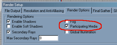
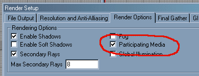
The first thing we need to do is to enable
"Media" in the "Render Setup". Otherwise participating
media and subsurface scattering would not be used.
|
|
|
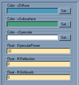
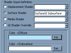
In the "Shading Editor" under
"Materials Editor", select the "Material Subsurface"
material. Select "SurfaceGI Subsurface"
shader for the surface shader. Setup the shader as shown on the left image. For the blue color use (0.3, 0.6, 0.75), and for the green color
use (0.3, 0.6, 0.5). The preview will be dark, but do not worry about
it, since usually most of the contribution comes from the subsurface
illumination with the current subsurface scattering shaders.
|
|
|
In the "Subsurface Scattering" section,
enable subsurface scattering. Leave the other parameters unchanged.
Translucency controls how far the light rays travel in the material before
reducing their intensity by 50%. Diffuse reflectance controls the light
intensity - Later on try different values to see how it affects the surface
appearance.
|
|
|
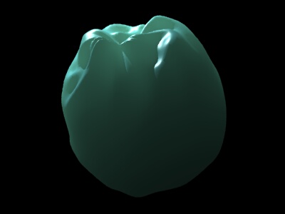
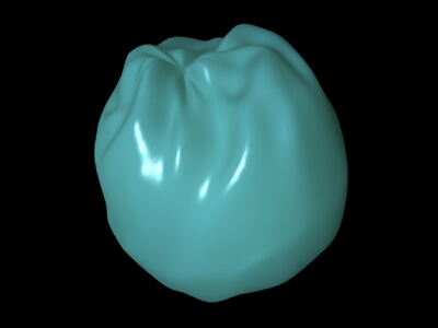
Rendering the scene and we get the following image.
The image clearly shows the light passing through the object as it would
happen in naturally translucent objects.
|
|
|
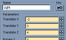
Now let’s adjust the light position to
see how the surface appears when it is also partially directly illuminated.
Set the light position to (-3.0, 3.0, 4.0).
|
|
|
Now we can also see the nice specular
highlights and bright illumination on part of the surface, but we still see
the subsurface illumination being the dominant.
|
|
|
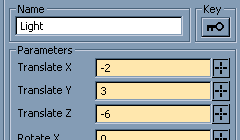
Finally let's adjust the light to be in front
of the object to completely illuminate its surface. Set the light position to
(-2.0, 3.0, -6.0).
|
|
|
The surface looks different, but it still
looks very smooth and translucent thanks to the underling subsurface light
transport.
|
Step 2 - Reducing
Translucency.
|
|
|
|
In this step we will reduce the translucency
parameter in order to make the subsurface effect "shallower" and
more local. By doing this we will be forced to solve some problems with the
irradiance samples that are used to compute subsurface scattering. You can
now download the lathed object scene: Download
"Tutorial 5" Lathed Object Scene. In the "Shading
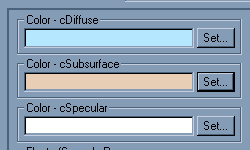
Editor" under "Materials", set the surface shader to "SurfaceGI Subsurface" and adjust the "cDiffuse" color to (0.7, 0.9, 1.0).
|
|
|
The surface looks very dark and hard when
rendered. For now that is ok, because subsurface scattering is going to
provide most of the illumination with this shader.
|
|
|
Back in the "Shading Editor",
adjust the "cSubsurface" color to (0.9,
0.8, 0.7).
|
|
|
Enable "Subsurface Scattering",
and adjust "Translucency" to 0.5.
|
|
|
And of course, enable "Media" in
"Render Setup".
|
|
|
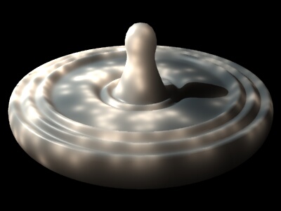
If we render the scene right now, we will see
the following image. It looks much brighter, but it also has a lot of these very
annoying dots. They are there because there is not enough
irradiance samples. Usually when we reduce the translucency and make the
subsurface scattering effect more local, we also need to increase the number
of irradiance samples. By default it is 1000. When rendering you also
probably noticed the following line in the output window: * Subsurface
Scattering points used: X, minimum recommended: Y. Y is usually the very minimum
needed and usually it is 10-20 times smaller than the actual number of
samples necessary. In the future it is likely to change, but for now it can
serve as kind of a guide.
|
|
|
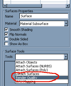
Having the object selected in the "Surfaces
Toolbar" select "Render Quality" tool.
|
|
|
In the "Subsurface Scattering
Points" increase the count to 10000.
|
|
|
The image looks better, but we still can see
the low frequency noise. We are going to further increase the point count and
reduce the error threshold.
|
|
|
In the "Subsurface Scattering",
properties of the material reduce the error threshold to 0.2. 0.5 is usually
a good value, but to achieve the best possible look for given number of
irradiance points, reduce it to 0.2 or 0.1. It will increase rendering time
thought.
|
|
|
Then again increase the irradiance point
count to 500000.
|
|
|
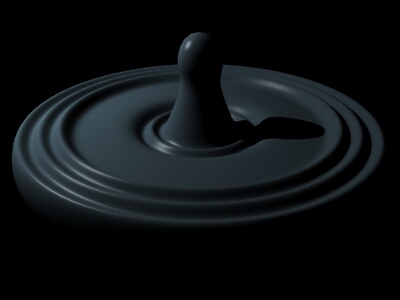
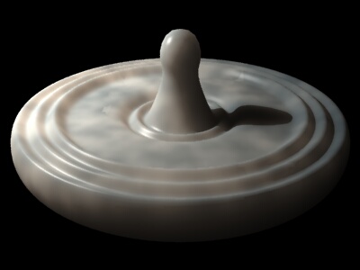
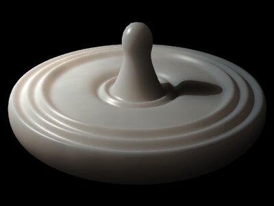
The final image. It looks pretty good!
|
